Induction is the topic that closes IB Physics HL Theme D — and it's where every single concept from D.1 to D.3 finally pays off. Topic D.4 is also notorious for two things: the angle convention in the flux equation $\Phi = BA\cos\theta$ (the most common arithmetic trap in HL physics) and the conceptual demand of Lenz's law (which the IB examiners love to combine with a sketching question). The good news: once you internalise that EMF responds to the change in flux, every D.4 question collapses into the same algorithm.
This cheatsheet condenses every formula, graph, trick and exam-mark trap from D.4 (AHL) into a one-page revision tool. Scroll to the bottom for the printable PDF, the full Notes, the Tutorial booklet, and the marked-up solutions in the gated full library.
§1 — Induced EMF & Magnetic Flux D.4 AHL
Key formulas
EMF in moving wire:$\displaystyle \varepsilon = Blv$
$N$-turn coil:$\displaystyle \varepsilon = BvlN$ (entering / leaving a field)
Magnetic flux:$\displaystyle \Phi = BA\cos\theta$
Flux density:$\displaystyle B = \frac{\Phi}{A}$
Unit:$1\;\mathrm{Wb} = 1\;\mathrm{T \cdot m^2}$
Note$\theta$ is the angle between $\vec{B}$ and the normal to the surface, NOT between $\vec{B}$ and the surface itself.
TrickIf a question states "the field makes angle $\alpha$ with the surface", convert: $\theta = 90° - \alpha$, so $\Phi = BA\sin\alpha$. Always re-read the question to confirm which angle is given.
TrapWhen a field reverses direction, $\Delta B = 2B$, so $\Delta\Phi = 2BA$, NOT $BA$. This factor-of-2 trap appears in nearly every Lenz/Faraday calculation.
§2 — Faraday's Law & Lenz's Law D.4 AHL
Faraday's law:$\displaystyle \varepsilon = -N\frac{\Delta\Phi}{\Delta t}$
Flux linkage:$\displaystyle \Lambda = N\Phi$ [unit: Wb]
Lenz's law — quick reference
- The induced current opposes the change in flux (not the flux itself).
- It is a direct consequence of the conservation of energy.
- An approaching magnet $\to$ the coil repels it; a retreating magnet $\to$ the coil attracts it.
- Use the right-hand rule to convert "required induced $\vec{B}$" $\to$ "direction of induced current".
TrickFor rotating coils, always compute $\Phi_i$ and $\Phi_f$ separately (with their cosines), then $\Delta\Phi = \Phi_f - \Phi_i$. Do NOT assume $\Delta\Phi = BA$.
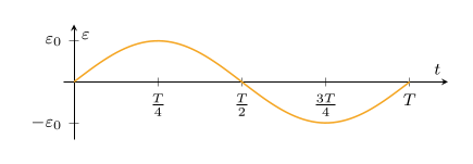
Trap$\varepsilon$ is maximum when $\Phi = 0$ (the flux is changing fastest at zero crossings). $\varepsilon = 0$ when $\Phi$ is at a maximum or minimum (flux is momentarily not changing). The two graphs are 90° out of phase — sine vs cosine.
§3 — AC Generator D.4 AHL
AC generator output: $\varepsilon(t) = \varepsilon_0 \sin(\omega t)$ — a pure sinusoid with peak $\varepsilon_0 = NBA\omega$.
Sinusoidal EMF:$\displaystyle \varepsilon = \varepsilon_0 \sin(\omega t)$, $\varepsilon_0 = NBA\omega$
Angular velocity:$\displaystyle \omega = 2\pi f = \frac{2\pi}{T}$
Effect of doubling rotation speed
| Quantity | Original | Doubled speed |
|---|
| Frequency $f$ | $f$ | $2f$ |
| Period $T$ | $T$ | $T/2$ |
| Peak EMF $\varepsilon_0$ | $NBA\omega$ | $2NBA\omega$ |
Doubling the rotation rate increases both amplitude AND frequency — the graph becomes "taller and narrower".
TrickOn a generator graph, if at $t = 0$ you have $\varepsilon = \varepsilon_0$ (maximum), then the coil plane is parallel to $\vec{B}$ (the normal is $\perp$ to $\vec{B}$, so $\Phi = 0$ at that instant). If $\varepsilon = 0$ at $t = 0$, the plane is $\perp$ to $\vec{B}$ (and $\Phi$ is at its maximum).
§4 — RMS Values & AC Power D.4 AHL
RMS = root-mean-square: time-average of $I^2$ then take the square root, giving the equivalent DC current that delivers the same power.
RMS current:$\displaystyle I_{\mathrm{rms}} = \frac{I_0}{\sqrt{2}} \approx 0.707\,I_0$
RMS voltage:$\displaystyle V_{\mathrm{rms}} = \frac{V_0}{\sqrt{2}} \approx 0.707\,V_0$
Average power:$\displaystyle \bar{P} = \tfrac{1}{2}I_0 V_0 = I_{\mathrm{rms}} V_{\mathrm{rms}} = I_{\mathrm{rms}}^2 R = \frac{V_{\mathrm{rms}}^2}{R}$
Peak power:$\displaystyle P_0 = I_0 V_0 = 2\bar{P}$
TrapIf you are given the peak voltage on a transformer's primary, find the peak secondary voltage first (using the turns ratio), and only THEN divide by $\sqrt{2}$ to get the RMS. Doing it in the wrong order is a common arithmetic slip.
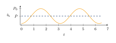
NoteThe instantaneous power graph $P = I_0 V_0 \sin^2(\omega t)$ has twice the frequency of the $V$-$t$ graph and is always $\geq 0$. The mean of $\sin^2$ over a full cycle is $\tfrac{1}{2}$ — that's where the $\sqrt{2}$ in RMS comes from.
§5 — Self-Induction D.4 AHL
Self-induction: when current changes, the back-EMF opposes the change — current rises (or decays) exponentially toward steady state.
Instantaneous current:$\displaystyle I_{\mathrm{inst}} = \frac{V_{\mathrm{ext}} - \varepsilon_{\mathrm{back}}}{R}$ (inductor + resistor)
Key facts
- The back EMF opposes the change in current (Lenz's law).
- At switch-on: back EMF $= V_{\mathrm{ext}}$, so $I = 0$.
- Steady state: back EMF $= 0$, so $I = V_{\mathrm{ext}}/R$.
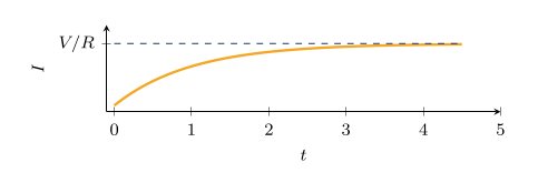
- The current follows an exponential growth curve toward $V/R$.
- Application: spark plugs — a sudden current break gives huge $\mathrm{d}I/\mathrm{d}t$ and a very large back EMF.
TrickIn IB exams, self-induction questions almost always ask you to explain the shape of the $I$-$t$ graph. Always mention all four points: (1) back EMF opposes the change in current, (2) as $I$ increases, $\mathrm{d}I/\mathrm{d}t$ decreases, (3) so the back EMF decreases, (4) hence $I$ approaches $V/R$ asymptotically.
§6 — Exam Attack Plan All sections
When you see this in the question — reach for that:
| Question trigger | Reach for |
|---|
| "EMF in a wire moving through $\vec{B}$" | $\varepsilon = Blv$ (or $BvlN$ for $N$ turns) |
| "Flux through a coil at angle $\alpha$ to surface" | $\theta = 90° - \alpha$, so $\Phi = BA\sin\alpha$ |
| "Average EMF over a time interval" | $\varepsilon = N\,\Delta\Phi/\Delta t$ — compute $\Phi_i$ and $\Phi_f$ separately |
| "Direction of induced current" | Lenz: induced $\vec{B}$ opposes the change in flux; right-hand grip gives current direction |
| "Field reverses direction" / coil flipped | $\Delta B = 2B$, so $\Delta\Phi = 2BA$ — don't lose the factor of 2 |
| "Peak EMF of generator" | $\varepsilon_0 = NBA\omega$ where $\omega = 2\pi f$ |
| "Effect of doubling rotation rate" | Frequency doubles AND amplitude doubles ($\omega \to 2\omega$) |
| "Mean power in AC circuit" | $\bar{P} = I_{\mathrm{rms}}V_{\mathrm{rms}} = V_{\mathrm{rms}}^2/R$ |
| "Convert peak to RMS" | Divide by $\sqrt{2}$ — but apply transformer ratio first if relevant |
| "Why does inductor current rise gradually?" | Back EMF opposes change — quote all four steps |
Worked Example — IB-Style Rotating Coil
Question (HL Paper 2 style — 7 marks)
A rectangular coil of $N = 200$ turns and area $A = 80\;\mathrm{cm^2}$ rotates with frequency $f = 50\;\mathrm{Hz}$ about an axis perpendicular to a uniform magnetic field $B = 0.040\;\mathrm{T}$.
(a) Calculate the angular velocity $\omega$. (b) Calculate the peak EMF $\varepsilon_0$ generated. (c) Calculate the RMS voltage. (d) State the instant during the rotation when the EMF is zero, and explain why.
Solution
- Angular velocity (a): $\omega = 2\pi f = 2\pi (50) = 314\;\mathrm{rad\,s^{-1}}$ (M1)(A1)
- State peak EMF formula (b): $\varepsilon_0 = NBA\omega$ (M1)
- Convert area to SI: $A = 80\;\mathrm{cm^2} = 80 \times 10^{-4}\;\mathrm{m^2} = 8.0 \times 10^{-3}\;\mathrm{m^2}$ (R1)
- Substitute (b): $\varepsilon_0 = (200)(0.040)(8.0\times 10^{-3})(314) = 20.1\;\mathrm{V}$ (A1)
- RMS (c): $V_{\mathrm{rms}} = \dfrac{\varepsilon_0}{\sqrt{2}} = \dfrac{20.1}{\sqrt{2}} = 14.2\;\mathrm{V}$ (A1)
- Zero EMF instant (d): $\varepsilon = 0$ when the coil's plane is perpendicular to $\vec{B}$ — equivalently, when $\Phi$ is at its maximum (or minimum). At that instant $\mathrm{d}\Phi/\mathrm{d}t = 0$, so by Faraday's law $\varepsilon = 0$. (A1)
Examiner's note: Two punishing errors. (1) Forgetting to convert $\mathrm{cm^2}$ to $\mathrm{m^2}$ — a factor of $10^{-4}$ that destroys every subsequent answer. (2) Saying "EMF is zero when the flux is zero". That is the OPPOSITE of the truth: EMF is zero when the flux is maximum (instantaneously not changing), and EMF is maximum when the flux is zero (changing fastest). Sketch a sine and cosine on the same axes to fix this in muscle memory.
Common Student Questions
What is the angle $\theta$ in $\Phi = BA\cos\theta$?
$\theta$ is the angle between $\vec{B}$ and the normal (perpendicular) to the surface, NOT between $\vec{B}$ and the surface itself. So if a question says "the field makes an angle $\alpha$ with the surface", then $\theta = 90° - \alpha$ and $\Phi = BA\sin\alpha$. Misreading this is the single most common sign/factor error in D.4.
When is the induced EMF a maximum in a rotating coil?
EMF is maximum when the flux is changing fastest — which happens when the flux itself is zero. That is, when the coil plane is parallel to $\vec{B}$ (the normal to the coil is perpendicular to $\vec{B}$). Conversely, the EMF is zero when $\Phi$ is at a maximum or minimum, because at those instants $\Phi$ is momentarily not changing. Sketch a sine and cosine on the same axes — they are 90° out of phase.
What does Lenz's law actually say, and why does it matter?
Lenz's law: the induced current flows in the direction that opposes the change in flux (not the flux itself). It's a direct consequence of conservation of energy — if the induced current reinforced the change, you would get a runaway perpetual-motion machine. Practically, you use it to find the direction of the induced current: figure out which way $\Phi$ is changing, then the induced $\vec{B}$ must point opposite to that change, and the right-hand grip rule gives the current direction.
How do I convert between peak and RMS values?
For a sinusoidal AC signal: $I_{\mathrm{rms}} = I_0/\sqrt{2} \approx 0.707 I_0$, and similarly $V_{\mathrm{rms}} = V_0/\sqrt{2}$. To convert RMS to peak, multiply by $\sqrt{2}$. The average power equation $\bar{P} = I_{\mathrm{rms}} V_{\mathrm{rms}}$ is the practical reason RMS values exist — they let you treat AC like DC for power calculations. Singapore mains voltage of "230 V AC" is the RMS value; the peak is about 325 V.
What happens to the induced EMF if a magnetic field reverses direction?
If $\vec{B}$ reverses (e.g. flipping a coil over, or $B$ going from $+B$ to $-B$), then $\Delta B = 2B$, not $B$. So $\Delta\Phi = 2BA$, doubling the EMF compared to a same-magnitude change without reversal. This "factor of 2" trap appears in almost every Lenz/Faraday calculation paper question — write down both $\Phi_{\mathrm{initial}}$ and $\Phi_{\mathrm{final}}$ explicitly with signs.
What's NOT in this cheatsheet
This page gives you the formulas and the traps. The full Photon Academy Induction library (only available to enrolled students or via the resource library subscription) adds:
- Notes PDF — every concept worked through in full, with derivations and intuition.
- Tutorial booklet — IB-style questions sequenced from foundation to AHL difficulty.
- Tutorial Solutions — full mark-scheme-style worked solutions with M1/A1/R1 annotations.
- Practice Solutions — extra past-paper-style problems with detailed walk-throughs.
- Cheatsheet PDF — print-ready, brand-formatted, the same one our students take into mock exams.
Get the printable PDF version
Same cheatsheet, formatted for A4 print — keep it next to your study desk. Free for signed-in users.